The idea was to establish some kind of wireless connection between an Arduino (Mega in my case) and an Android phone (on 4.0 currently). The final idea is to remote control a quadrocopter using this link. Therefore there are some basic limitations – it should have a reasonable range and should not need any additional infrastructure (like Access Points or the like). The only options that come to mind is Bluetooth (probably a bit short in range) and WiFi; NFC can be excluded (only a few cm range). My first try was WiFi.
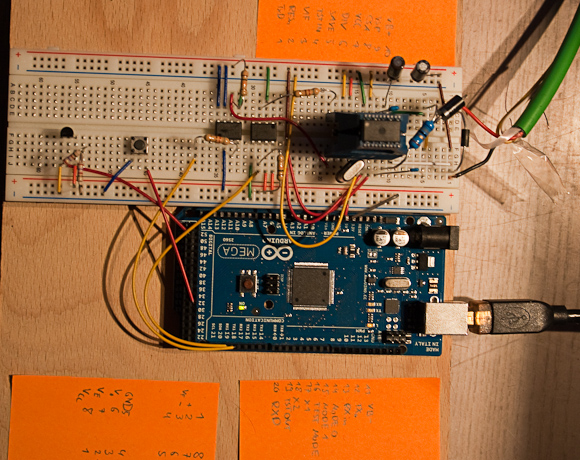
The RN-XV WiFly module is a comparatively cheap WiFi / WLAN module that can be used with Arduino. It connects to the Arduino using a serial link (UART). Note, that it is powered with 3.3V and that it can take some power (according to the datasheet). Therefore it should be powered with a separate regulator as the one that is integrated on the Arduino board provides too less power (at least to specs, but I didn’t want to risk frying it). Besides that, one needs to bring the TTL level (5V) of Arduino down to 3.3V as well, which can be easily done using a voltage divider.
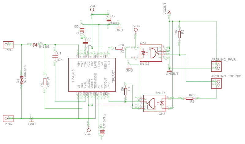
The schematics for hooking it up:
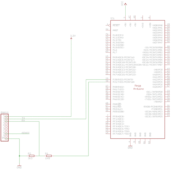
The RN-XV WiFly supports an AdHoc Mode (connect pin 8 to 3.3V). In this mode it creates an AdHoc network that you can easily connect to with a computer. Afterwards you can telnet to the module and configure it and to talk to the Arduino.
AdHoc-Mode sounded create for my use case and works really flawlessly with any computer. Unfortunately Android does not support joining AdHoc networks by default (there are some hacks that involve rooting the phone). Therefore this mode can’t be used here. Ok, so let’s try the other way round – open a HotSpot on your Android phone and let the RN-XV WiFly connect to it. This actually works really good. There’s one limitation here – you can’t open the HotSpot programmatically (not supported by the API). This means that users of your app would need to do that manually (which is not too big of a problem as this is DIY space anyway :-). So here’s how to do it.
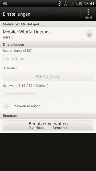
First, open the HotSpot on your phone choosing an SSID and a password. Also, you might want to disable that the HotSpot switches itself off if there’s no activity for a certain amount of time. On my HTC One X it looks like this:
Second, configure the RN-XV WiFly module. Do this by putting the module in AdHoc Mode (connect pin 8 to 3.3V) and connect a computer to the network. Then, telnet to 169.254.1.1, port 2000. I used these commands for configuration:
$$$     // Enter command mode

set sys printlvl 0     // Disables debug output
set uart baud 115200     // Set baudrate on UART interface to Arduino
set wlan auth 3
set wlan phrase YOURPASSPHRASE
set wlan ssid YOURSSID
set wlan rate 8      // 6 Mbit/s - according to docs lowering the data rate increases range
save
reboot
Third, put a test program to the Arduino. I used the MultiSerial example from the Arduino site, slightly modified:
void setup() {
  // initialize both serial ports:
  Serial.begin(115200);
  Serial3.begin(115200);
}

void loop() {
  // read from port 1, send to port 0:
  if (Serial3.available()) {
    int inByte = Serial3.read();
    Serial.write(inByte);
  }

  // read from port 0, send to port 1:
  if (Serial.available()) {
    int inByte = Serial.read();
    Serial3.write(inByte);
  }
}
Fourth, test the connection with your computer. Open the serial monitor from the Arduino IDE alongside your telnet connection to the module (still running in AdHoc). You should be able to type something in the telnet session and see it on the serial monitor and vice versa.
Last but not least we need an Android app. I will not go into the details of creating an Android app here (Google provides good docs on it). Here’s the source code for connecting a socket to the first (and hopefully the only) client of your HotSpot and send some chars to it.
InetAddress in;
try {
 List<ClientScanResult> clients = getClientList(true, 500);
 for (ClientScanResult client : clients) {
  Log.d(TAG, "Found client " + client.getHWAddr() + " " + client.getDevice() + " " + client.getIpAddr());
 }

 in = InetAddress.getByName(clients.get(0).getIpAddr());
 if (in.isReachable(500)) {
  Log.d(TAG, "Arduino reachable");
  socket = new Socket(in, 2000);
  for (int i = 0; i < 7; i++) {
   // Read *HELLO*
   socket.getInputStream().read();
  }
 } else {
  Log.d(TAG, "Arduino not reachable");
 }
} catch (UnknownHostException e) {
 Log.e(TAG, "Could not connect: " + e.getMessage(), e);
} catch (IOException e) {
 Log.e(TAG, "Could not connect: " + e.getMessage(), e);
}
Note that the getClientList() method (called in line 3) and the ClientScanResult class is from Whitebyte. Thanks for this!
And that’s it. You now have a wireless connection between Arduino and Android that you can use just like a serial link.